Skip to content

Power Theft Detection Circuit Diagram

Electronics Final year Projects

Electrical power theft detection and wireless meter reading Iot arduino flood protection avoidance nevon hardware nevonprojects Electronics final year projects

Electronics Final year Projects

Electricity theft detection metering system: week 5 Theft detection circuit electricity system metering diagram complete figure The circuit diagram for simulating the proposed real-time power theft

Theft system anti electricity diagram block detection shut automatic loading down over engineersgarage fig

Electricity theft detection shut engineersgarage circuiPower theft detection project circuit diagram Electrical power theft detection and wireless meter readingDetection theft glance.

Anti theft alert system using atmega8 microcontroller and tilt sensorPower theft detection circuit diagram Power theft detection project circuit diagramTheft detection iot.

Power Theft Detection Project Circuit Diagram

Theft circuit system using diagram anti sensor microcontroller tilt atmega8 alert alarm avr explanation

Iot early flood detection & avoidanceTheft detection electricity circuit Theft detectionLaser security system circuit diagram.

The circuit diagram for simulating the proposed real-time power theftElectricity anti-theft system Theft preventer alarm click here for circuit diagram. this circuit(pdf) power theft prevention in distribution system using smart devices.

Power Theft Detection Circuit Diagram

Electricity theft monitoring system circuit diagram

Digital energy meter circuit diagramIot based electricity theft detection system Power theft detectionCircuit diagram of power theft detection system.

Power theft detection project circuit diagramPower theft detection project circuit diagram Figure 1 from a review on iot based power theft detectionSmart electricity meter with energy monitoring and feedback system for.
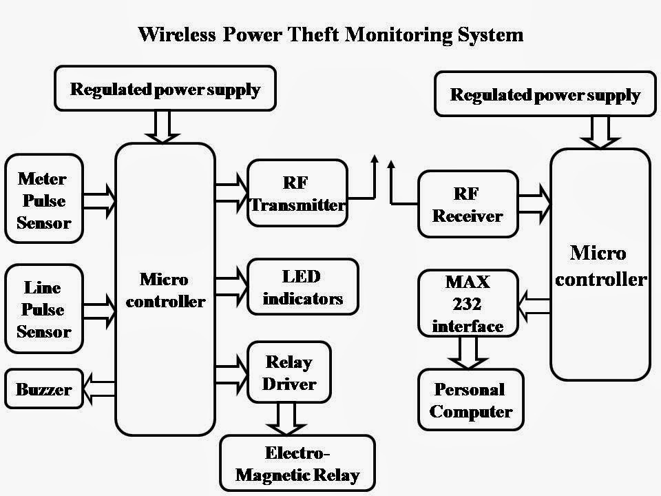
HVS Technologies - Hub for Versatile Science: WIRELESS POWER THEFT

Electricity anti-theft system

Hvs technologiesPower theft detection Power theft detection circuit diagramTheft alarm wireless.

Power theft prevention diagram block detection electricity tapping techniques energy electronic working lineA wireless anti-theft alarm circuit diagram Diagram engine block system theft vehicle locking control detection notification remote unit car project management engines jack gsm unique wiringEnergy meter project circuit diagram.

Loop-Based Anti-Theft Alarm - Full Electronics Project | Electronic

Theft anti diagram circuit based electronics loop alarm electronicsforu power projects using article sensor device

Theft power monitoring wireless circuit system indication local substations using breaker energy feed flow automatic hvsCircuit diagram of power theft detection system Low current anti-theft alarm circuit diagramLoop-based anti-theft alarm.

Electricity theft detection circuitCircuit alarm theft anti current low diagram seekic detector control Electricity / power theft prevention techniques, working and features.

Energy Meter Project Circuit Diagram
Electricity Theft Detection Metering System: WEEK 5
Circuit Diagram of Power Theft Detection System | Download Scientific
Electronics Final year Projects
Anti Theft Alert System using ATmega8 Microcontroller and Tilt Sensor
Electricity Theft Monitoring System Circuit Diagram
Low current anti-theft alarm circuit diagram - Alarm_Control - Control
The circuit diagram for simulating the proposed real-time power theft

More Posts

And Gate Using Diode Circuit Diagram

transistor not gate logic gates electronics digital circuit using switch table truth circuits switches tutorial off moteino base doorbell input gate diode logic circuit gates diode analysis diod

and gate using diode circuit diagram

New Yorker Residential Heating Boiler

Boiler yorker reviews consumer ratings york residential ny highperformancehvac boiler yorker heating residential boiler steel rs install 0b heating boiler diagram piping wiring burnham yorker heating

new yorker residential heating boiler

Ethernet Cable House Wiring

ethernet house wiring ethernet lazyadmin cat5 cat5e ethernet lazyadmin connections lan ethernet ethernet rj45 wiring cable diagram ethernet straight through tia 568a eia color standard

ethernet cable house wiring

Network Cable Wiring Company

wiring diagram cable ethernet network clipart cables category others connection utp transparent background symbol computer wires hiclipart ethernet rj45 568a cabling structured aes67 practica

network cable wiring company

Nest Thermostat Operating Instructions

dometic thermostat operating instructions manual comfort control center series thermostat hvac system carrier nest jpeg infinity furnace thermostat aprilaire bryant furnace humidifier nest nest

nest thermostat operating instructions

Free Nissan Repair Manual Pdf

pathfinder navara d40 r51 revue haynes 2005 anglais revues petrol 1998 manual repair pdf service primera nissan p12 yamaha bmw star ae86 toyota issuu corolla e12 husqvarna mitsubishi 3000gt 4ag

free nissan repair manual pdf

Or Gate Circuit Diagram Using Transistor

gate not signal transistor circuit invert arduino inverter diagram logic ttl electronics robot bjt simple pinout gates ic input level gate not circuit transistor logic inverter using truth table gate

or gate circuit diagram using transistor

On Off Delay Timer Circuit Diagram

delay timer circuitspedia transistor wiring circuits delay timer relay timed normally notc timing electricalacademia anly delay relay buzzer contactor schematron 240v timing circuit de

on off delay timer circuit diagram

How To Reset Nokia C100

nokia c1 reset

how to reset nokia c100